
Preface
The build page is designed to be a living record of knowledge gained from the racing and testing of the PartsBadger Miata #630. In this page we will do our best to document our development efforts, sources of information, and most importantly our failures.
Overview
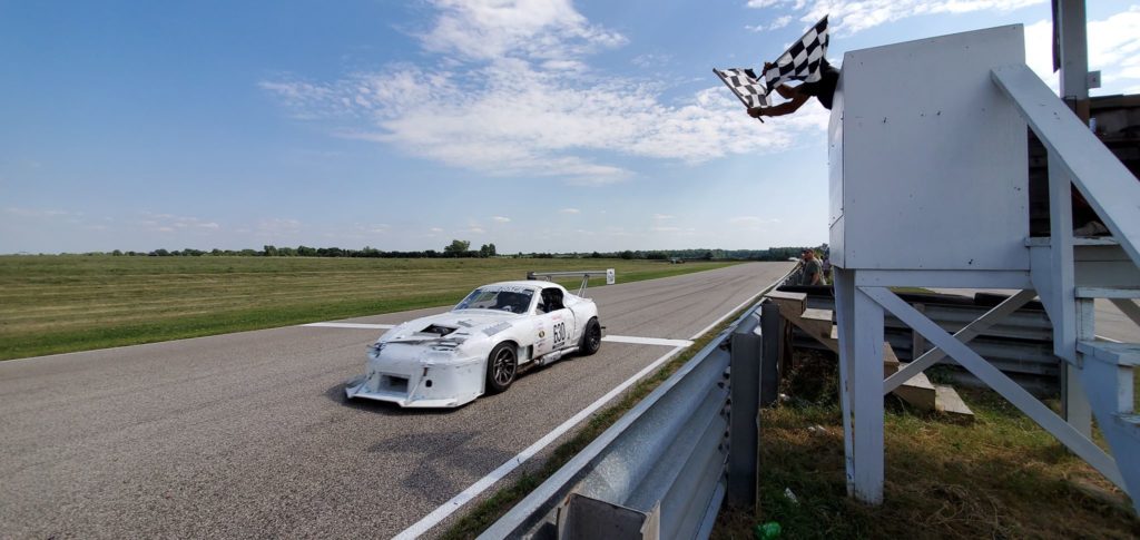
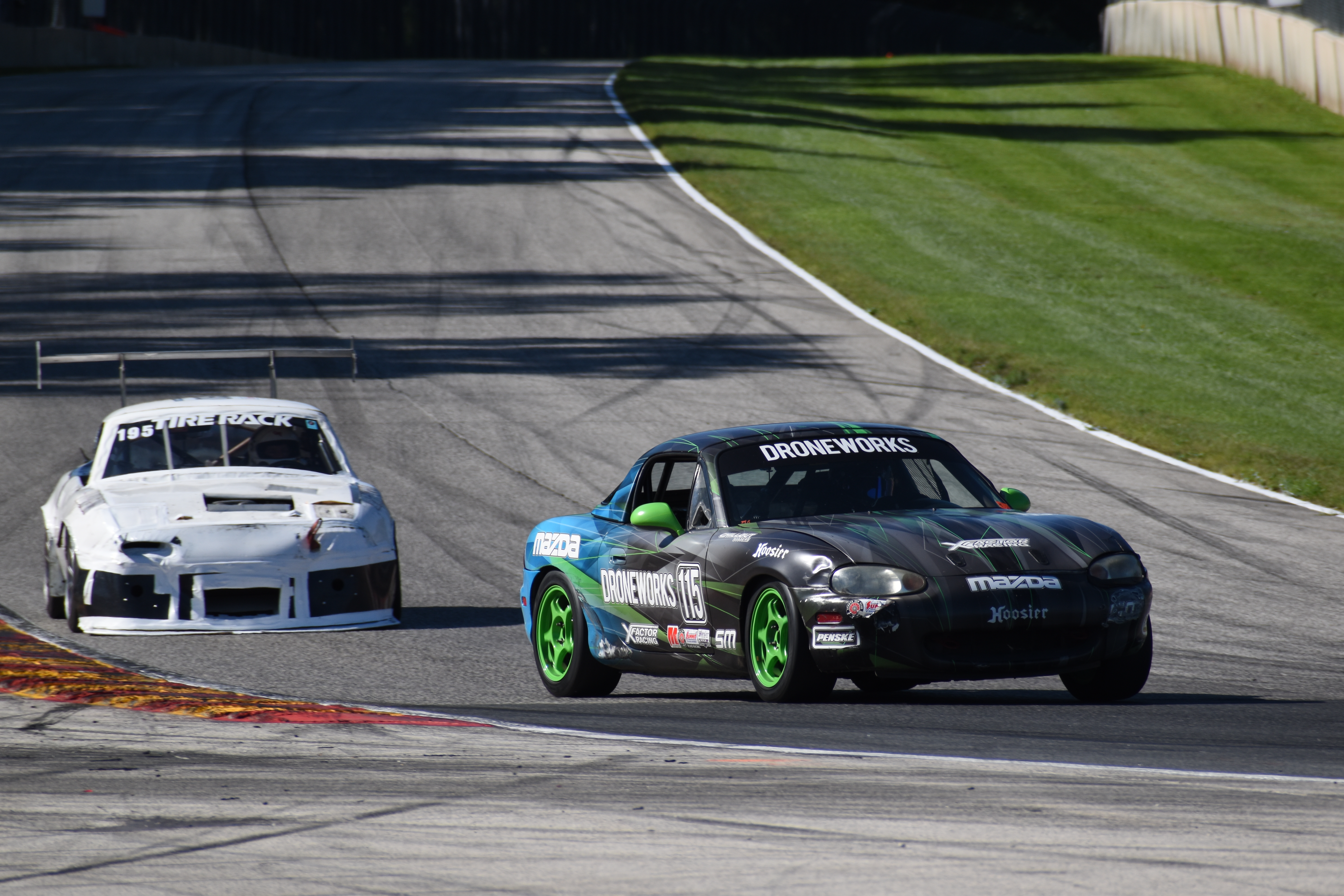
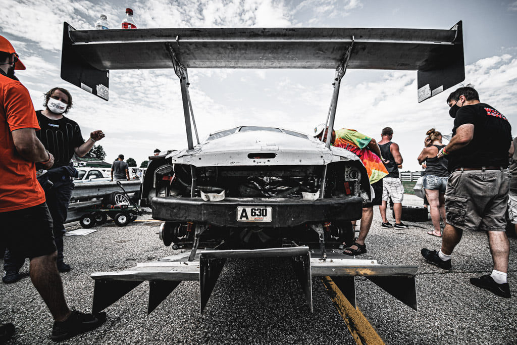
Racing within the ChampCar Endurance Racing Series, Rugged Badger Racing has prepared the PartsBadger – 1990 Mazda Miata #630. Prepared to the limits of the rules, the PartsBadger Miata is the fastest Mazda powered Miata in the series.
Suspension/Chassis
Our baseline suspension was selected based on three decades of combined miata racing experience. We knew we would want slightly stiffer springs in the front and much stiffer springs in the rear vs. spec miata. The intent is to stay off the bumpstops but to also account for the added downforce. Most of the following Miata race parts can be found here.
Suspension Components
- Springs – 850/450 Eibach *Moved to 900 on the LF.
- Front Spring PN: 0600.250.850 & 0600.250.900
- Rear Spring PN: 0600.2530.0450 (Barrel)
- Shocks – Bilsteins (Moved to SM Penskes)
- Bumpstops – 5X Racing 36mm Race
- Perches – Ground Control
- Front Sway – Swapped as needed (RB hollow is 5lbs lighter and 30% stiffer than SM), SM, FlyinMiata, Stock and Drilled Stock
- Rear Sway – Stock and SM
- Bushings – Delrin (Contact me if you want some)
The most difficult challenge with the Miata suspension is the lack of travel which can result in an abrupt increase in spring rate which unsettles the car. The concern is not only on rumble strips, but also when transitioning quickly in corners like the inner loop at WGI, or the motorcycle bend at Road America. We chose spring rates high enough they would be able to support these conditions while not abruptly hitting the bumpstop. When you purchase springs, be sure to get barrel springs in the rear. This will prevent the spring from rubbing on the coilover perch.
Just as important as spring rates are the bump stops themselves and we’ve had great performance from the 5XRacing 36mm bumpstop. In addition to travel issues of the shock itself, we’ve also has issues with our 245/40-15 RS4s rubbing on the inside wheel well with both the 9″ and 10″ rims. Since the heavy corner of the car is the left front and this is where the rubbing is the most pronounced, we increased the spring rate in that corner.
We’ve gone through a number of front sway bars. Adding more front bar really helps settle the rear of the car especially on braking and turn in and it allows for a more consistent drive-ability. More over it allows the car to rotate in a more controlled manner which allows the drive to get on the throttle earlier. The overall speed potential is likely similar, but a front bar provides consistency. We wanted the points in other areas so we are running the stock front bar. The rear sway bar causes more rotation on turn in and mid-corner. Its possible that a rear bar would allow you to run less toe out in the front, but we have not tested this. We’ve tested rear bar settings at Road America and our notes were that the car felt faster and easier to drive with less rear bar, although there was no appreciable impact on times. Since the Miata naturally rotates it would be our recommendation to save the 20pts and use the stock rear bar.
Penskes Update
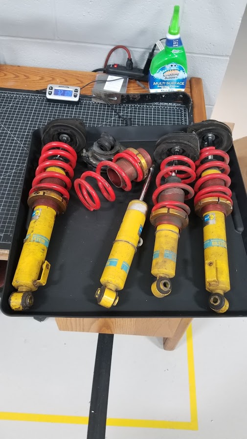
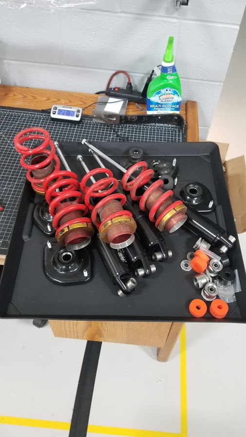
32lb 11oz vs. 27lb 8oz (Saves 5lb 3oz overall)
PartsBadger ran 2019 with standard Spec Miata Bilsteins, with 850/900 and 450 springs. We switched to Penskes for 2020 and these are our notes:
- Penskes are officially 2X but require a coil-over so they are 40pts. This includes modified 99 top hats.
- The Complete Penske Setup is 5lbs 3.3oz lighter than Bilsteins total.
- Penskes require 99 hats and modifications. They are a bitch to drill out for the modification but mazda now sells them pre-modded.
- Penskes installation instructions have an additional rubber keeper on the spring that we were not running before. We estimate this impacts ride height ~0.2″ however the spring mount also seems higher on the 99 hats, which then lowers the ride height some vs. Bilsteins.
New Penskes also come with the threaded body reducing mass further and improved cooling. We still have the first generation.
Driving Notes:
Overall the car is just smoother. I believe this is a combination of the additional rubber spacer on the spring, but it was audibly quieter and we could go full-send over all the rumbles without the car straining. With the bilsteins it just felt a little more strained and that you are stressing things mechanically. We would still go full send with the Bilsteins, but I felt bad about it. I did not feel a speed difference directly, but we also had many other aero changes and didn’t test back-to-back. At a track like Sebring, I could see a much bigger advantage. At a smooth track and/or low rumbles there is likely no difference between Penskes and Bilsteins.
The car was maybe 1.5-2 seconds faster in 2020 vs. 2019 at Road Atlanta, but I believe most of that is aero and weight changes, and a couple tenths are attributable to the Penskes.
Alignment
- Ride Height – 4.375″ front and 4.875″ rear (Changing with Flat Floor)
- Camber – 2 degrees rear, 1.8 degrees front
- Caster – 4 degrees
- Toe – Front (1/16 to 1/4 out),
- Rear 1/16″ Toe In
Ride Height – This has not been verified but it is recommended that cars run a positive rake angle, where the rear of the car is higher than the front. This allows for the air under the car to accelerate, like a diffuser, which helps reduce lift on the car. We chose the ride height to allow for enough suspension travel to avoid spikes in effective spring rate from the bumpstops. These measurements are taken from the ground to the pinch weld by the jack points.
Camber – We use a pyrometer to measure tire temperatures and temperature profiles across the tire which we use to find the ideal alignment of our car, more on that can be found here. Based on our data it supported we run camber numbers and tire pressures much lower than conventional running at less than 2 degrees. Another component of this that our chassis is likely stiffer than normal due to welding the cage in strategic locations. Delrin bushings also mean less flex between the arms and subframe. As we reduce camber and tire pressures we are able to put down more power sooner and get more overall grip from the tires. This also helps keep wear and heat even across the tire.
Caster – Initial alignments maximized our front caster. This should increase handling, but it also increases steering weight. We’ve dialed that back to 4 degrees on both sides, which is a good trade off versus 5 degrees and saves our arms a little bit.
Toe – Front toe helps the car turn in, however you sacrifice stability under braking and straight line speed. On short tracks we will run more toe (3/16-1/4), and on long tracks we will sacrifice turn in performance for the reduced drag on the straights by running less toe (1/16-1/8″). Where we run toe-out in the front, in the rear toe-in provides stability. For earlier races we had run zero toe and toe out in the rear which helped keep heat in the tires and created a very “fun” car, however we decided to use a more conservative setup in an effort to reduce driver workload.
Wheels, Tires & Hubs
- Tires: 245/40-15 RS4 (Hankook) Hot Pressures around 24 PSI
- Wheels: 15x10’s or 15x9’s
- Wheel Bearings: OEM Repack with Neolube
- Wheel Studs: ARP Hubs: Centric non-economy or OEM.
Tires – The 245/40-15 Hankook RS4 appears to be the best tire for the Mazda Miata. It has been generally known, but not explicitly tested by us that the Bridgestone RE71-R is a better compound but sizes are limited for the Miata. The RE71-R compound seems to wear much faster, upto 3 times faster, than the RS4. We plan on testing the 285/30-18 RE71-R later in 2019. Testing between the 245/40-15 RS4 and the 225/45-16 Dunlop StarSpec II was performed at Road America and that tire was 0.5 second slower per lap. The tire performed much better under braking, but lacked the lateral grip of the RS4.
Wheels – We’ve tried the 15x9 6UL(36ET), 15x10 Jongbloed(25ET), and the 15x10 Konig Dekagram(25ET). Times have been very similar when comparing the 9″ to the 10″ rim and back-to-back testing was that the 15x10 may be just the smallest amount faster, however they appear less durable than the 15x9. Almost all on the Jongbloed’s have cracked or bent, where the 6UL has taken substantial abuse with better structural integrity. We’ve had good luck with the Dekagrams as well and believe this is a much better rim than the Jongbloed.
Wheel Bearings/Hubs – We’ve moved from repacking hubs with Neolube from Redline CV2 based on a competitors input, however we’ve had zero issues with either. Buying spare hubs requires some effort because some of the castings which are then machined can fail by cracking where the flange meets the body. Centric has two part numbers to differentiate from normal hubs vs. hubs that DO NOT have the machining issue. DO NOT BUY: 405.45005E or 405.45006E (ABS) These are economy Timken bearings and have excessive machining. DO BUY: 405.45005 or 405.45006(ABS) These are NTN bearings and do not have excessive machining. Wheel Studs: We haven’t had a wheel stud failure and don’t really want to. We went with ARP studs to be on the safe side. ARP 100-7719 (90-93 Front and Rear, 94+ Front) ARP 100-7720 (94+ Rear)
Bushings – Per the ChampCar rules suspension bushings are zero points. Our car, a former ITA Miata, came with delrin bushings. When combined with the chassis stiffness of our car, delrin bushings help eliminate the suspension play and reduce the time it takes to “roll onto the camber” when transitioning into corners. We believe this is a key ingredient to our Miatas amazing handling. Delrin bushings are hard to source and we’ve decided to make these kits available for sale.
The Engine
Choosing an engine is one of the most important parts of our ChampCar build. Since its endurance racing, we need an engine that will last for extended periods of time, up to 24 hours, at race speed and allow the rest of the drivetrain to last. The Miata needs power to keep up on the fast tracks, and we need to stay within the rules of the series.
The Rules
ChampCar has three limits when it comes to engines; price(<$1500 for the swap, moving to $2500 in 2020), rated power output compared to the weight of the car, and the engine must be in a standard car on the VPI list. Within these rules there are a huge number of options, but only two are common and practical within the $1500 limit, Ecotec or 1.8L swap. In 2020 the K swap should be able to fall within the $2500 limit. A common choice is the Ecotec 2.2L (L61) or 2.4L (LE5) these motors are supposedly reliable, cheap, and the install kit is simple. After much research we found you could likely get a LE5 to put down between 165 and 180RWHP. There have been numbers reported of 200RWHP however we have not verified this. We do not have any confirmed power data for the L61, but a safe assumption is that its less than the LE5. Not included in the analysis below is the addition of aftermarket camshafts on the LE5 and L61 which have shown significant power gains, upwards of 20 RWHP however reliability has been an issue with those teams.
The other popular choice is to do a 1.8L swap with an NA8, NB1, or NB2(VVT) motor. If you swap the motor in an NA Miata, you then have to claim your car as a 1994-1997 and start with a base of 300pts, rather than the 250pts starting for the 1.6L Miata. This is due to a rule that requires you platform swap to the highest point version of the car if you swap the engine. With the platform swap you are allowed then to add the larger 1.8L fuel tank (12.7Gal) and 1.8L differential. The different Miata’s and their base points are listed below:
- NA6 – 1.6L Miata – 250pts (11.9gal, 6″ differential)
- NA8 – 1.8L Miata – 300pts (12.7gal, 7″ differential)
- NB – 1.8L Miata – 350pts (12.7gal, 7″ differential)
- NC – 2.0L MX-5 – 400pts (12.7gal, 7″ differential) *Reference Only
Within these options we evaluated the best combination of HP to points with and without an engine swap. Our HP estimates are based on research of dyno information we found online, or from Spec Miata. These numbers assume race weight and a fresh motor with shaved head and deck within factory specs. They also assume an ECU, intake and exhaust.
- 1990-1993 – NA6 – 120RWHP – 1950lbs – 250pts – 16.25lb/hp
- 1990-1993 – NA6 – 120RWHP – 1975lbs – 275pts – 16.46lb/hp (7″ Diff)
- 1990-1993 – NA6 – 125RWHP – 1975lbs – 300pts – 15.80lb/hp (7″ Diff, Header)
- 1994-1997 – NA8 – 125RWHP – 1975lbs – 300pts – 15.80lb/hp
- 1994-1997 – NA8 – 130RWHP – 1975lbs – 325pts – 15.19lb/hp
- 1999-2000 – NB1 – 135RWHP – 2075lbs – 350pts – 15.37lb/hp
- 1999-2000 – NB1 – 140RWHP – 2075lbs – 375pts – 14.82lb/hp (Header)
- 2001-2005 – NB2 – 135RWHP – 2075lbs – 350pts – 15.37lb/hp
- 2001-2005 – NB2 – 140RWHP – 2075lbs – 375pts – 14.82lb/hp (Header)
Swapped Combinations
Due to platform swap rules all 1990-1993 miata with an engine swap shall be considered a 1994-1997 and take the higher point value. Whats more, the rules do allow for a JDM engine swap, so long as the JDM engine is within 3% of the rated USDM HP. This is true for the NB1 engine, which comes with the square top intake manifold and the BP5A camshaft, good for a ~7 HP over USDM after a tune. In NB2 VVT form JDM engines are rated higher than the 3% allotted by the Champcar rules and thus are excluded from this analysis.
- 1990-1997 – NB1 – 135RWHP – 1975lbs – 350pts – 14.62lb/hp
- 1990-1997 – NB1 – 140RWHP – 1975lbs – 375pts – 14.11lb/hp (Header)
- 1990-1997 – NB2 – 135RWHP – 1975lbs – 350pts – 14.62lb/hp
- 1990-1997 – NB2 – 140RWHP – 1975lbs – 375pts – 14.11lb/hp (Header)
- 1990-1997 – LE5 – 165RWHP – 1975lbs – 401pts – 11.97lb/hp (Ecotec Swap)
- 1990-1997 – NB1 JDM – 142RWHP – 1975lbs – 350pts – 13.91lb/hp
- 1990-1997 – NB1 JDM – 148RWHP – 1975lbs – 375pts – 13.34lb/hp (Header)
By a wide margin the Ecotec motor allows for the highest power to weight ratio with only a 25-50pt hit over the most comparable options. So why aren’t we running the Ecotec?
JDM NB1 Engine
 When we decided to build our ChampCar we chose the NB1 engine despite the power advantage of the Ecotec simply because it was the engine we knew, and we wanted to sort the car before moving to an unknown engine. We purchased the JDM version off of ebay which turned out to be a lucky mistake. We soon found out we were blessed with two advantages: the square top intake manifold, and the BP5A cam. The intake manifold is good for a handful of HP in motors that breathe. The intake camshaft is also a slight bump since its timing is slightly advanced. Although we had planned to move to the Ecotec engine, we’ve been competitive at our current power levels and we have not wanted to regress in our progress towards reliability. Although the ChampCar rules, called the BCCR , allow for the JDM swap, expect additional scrutiny from tech. Be prepared to show receipts confirming you purchased a genuine JDM engine including intake manifold and header. We believe they will not allow competitors to purchase USDM engines and install JDM parts without claiming those points separately. In addition we also had to find a source that proves rated JDM power is within 3% of USDM power. After hours of searching and eventually “hacking” the URL on Mazda Japan website we were able to find archives from that era, which were otherwise not indexed or linked. The link to Mazda’s press release for the 1999 JDM Eunos Roadster (Miata) can be found here.
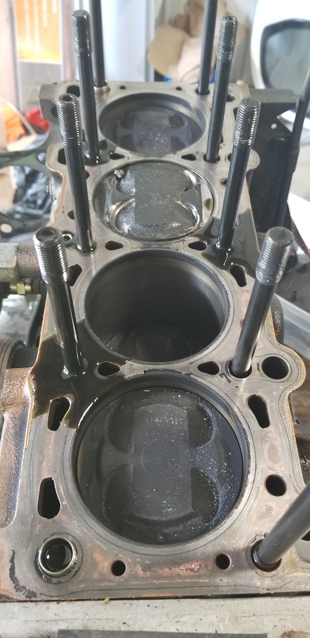
Rebuilding the Engine
Although some choose to run motors straight from the junkyard, we felt the investment was worth it to have the motor rebuild. During this process you will want to shave the head to the maximum of service limits, perform a valve job, and replace your valve springs with NEW oem springs. Shaving the head is worth some additional compression and also advances the cam timing which increases HP. We also strongly recommend ARP hardware for head, mains, and rods which is allowed at 0pts. It is strongly recommended to use Fel-pro gaskets. We’ve had failures of lower cost gaskets sold on Rock Auto. In addition it is legal to port and polish your head and intake manifold. For us a light port on the head was worth 1-3 RWHP. Additional porting could yield much better results. If the opportunity presents itself we will get a head sent out for professional porting by a Miata expert, especially since ChampCar rules are much more open that Spec Miata, we believe there can be significant gains. More information can be found here.
Engine Failures
Although the Miata engine has a history of reliability, we’ve pushed and exceeded the limits multiple times due to mis-information online and wishful thinking.
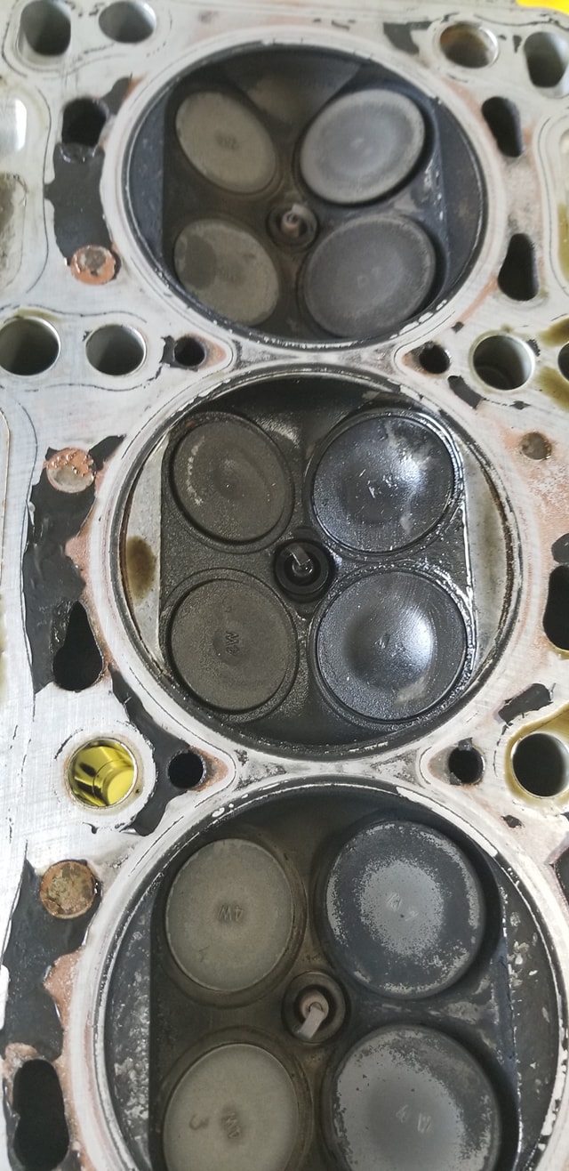
VIR South – (4hrs on engine) – Intake valves formed a ridge of wear which indicated valve float. The car was running good times and fast laps, as we pulled into the pits the car stalled and would not restart. During this race our cam timing was off a tooth, which we believe attributed to the issue at the time, but later found our was likely not a factor. It was later discovered that the cause of this error was valve float which seems to occur above 7100 RPM on a stock NB1 head. During these four hours the engine was rev’ed consistently past 7300 RPM and in some cases up to 7800 RPM. To correct this issue we purchased new valve springs from Mazda under the assumption that the old springs were heavily worn decreasing seat pressure.
Road America – (4hrs on engine) – Intake valves formed a ridge of wear which again indicated valve float. The car was running good times and fast laps, as we pulled into the pits the car stalled and would not restart. During this race the engine was rev’ed consistently past 7200 sometimes up to 7400 RPM. To correct this issue we set the rev limit to 7100 RPM.
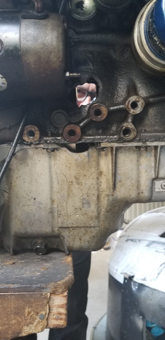
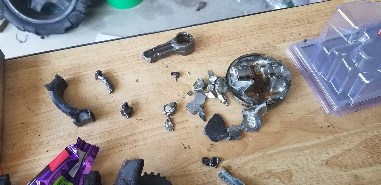
Watkins Glen – (14hrs on engine) – Engine threw a rod. After analysis we believe the case was a failure of a rod cap bolt which had sheered. To correct this issue we are rebuilding with 100% ARP hardware.
Engine Summary
The NB1 JDM variant is the best swap, mathematically, of the miata-family, but keep all your paperwork to prove its JDM to tech including intake manifold and header. A rebuilt engine with new valve springs, a shaved head and mild porting can produce between 145-149RWHP with a header. When rebuilding it is prudent to use ARP hardware all around and fel-pro gaskets. If you do not rebuild power levels could be ~20RWHP less which attributed to a 2.5 second reduction in time at Road America. The NB1 valvetrain does not support RPMs above 7100 RPM. Buying multiple OEM springs, measuring, and picking the best ones is strongly advised. Still, rev limits should be set at or below 7100 RPM and drivers should be aware of potential over-revs on downshifts because it will wear the lip on the valve and you will loose compression.
Dyno
Dynoed at: 151HP with Pulley and SD exhaust (Before Road America)
Dynoed at 125HP w/o pulley and bad self tune (After Sebring) *edited for accuracy
Dynoed at 145HP with custom exhaust and good tune (Before Road Atlanta)
Dynoed at 133HP with exhaust cam retarded a tooth and valve spring issues (Before VIR)
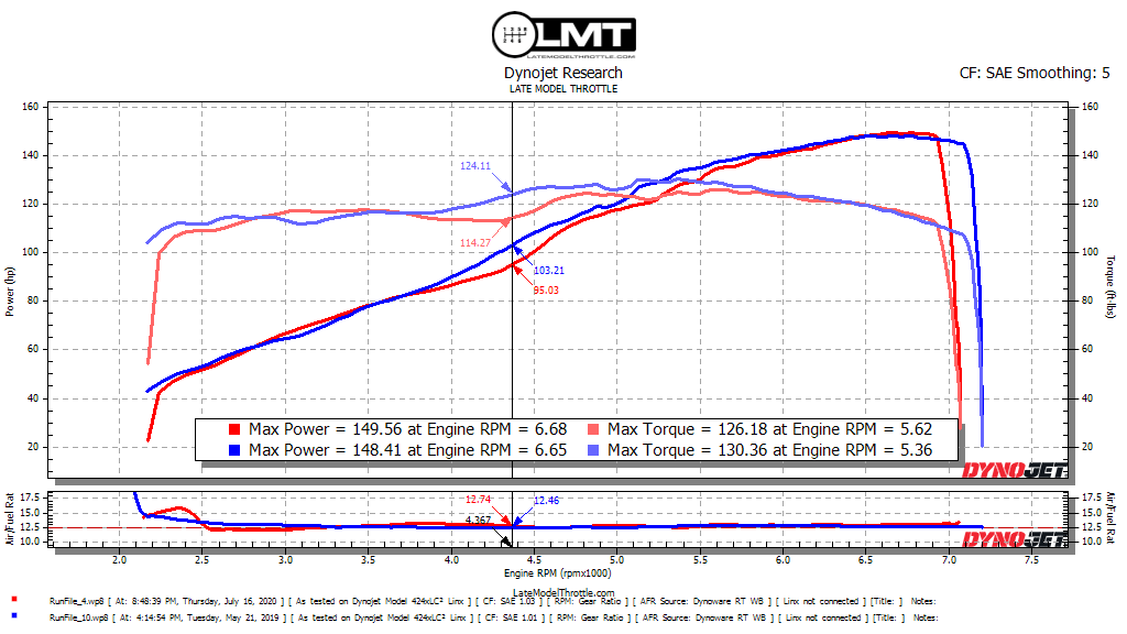
Dynoed at 148HP – Added Port and Polish – 21″ Intake (WGI) The dyno plot compares this tune (Blue) with the no-muffler run in Skunk2 Run. (Red) You can see the loss in torque between 3700 and 5800 RPM with a 10ftlb drop at peak.
Dynoed at 141HP – Modified JDM Tri-Y Header and Side Exhaust, 16″ Intake 2.5″
Dynoed at 147HP – with Skunk2 Intake Manifold 12.8 AF (Pre-Gingerman)
Dynoed at 146HP – with 13.5 AF (5% Fuel Save)
Dynoed at 144HP – with 14.2 AF (12% Fuel Save)
Dynoed at 150HP – with 12.8 AF – No Muffler (For Testing)
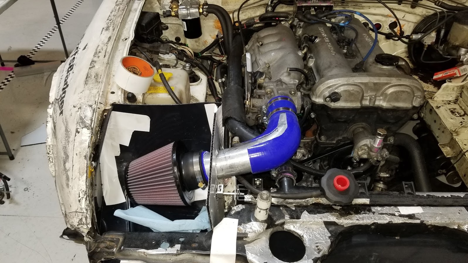
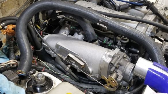
Intake
We had three goals for the intake on our engine: mounting the filter in cool air yet a high pressure zone, maintaining the optimal intake tract length of 21″, avoiding bends in the intake tract. To meet these goals, we used hardware to lower the radiator ~1.5″ and routed the 2″ intake pipe through the radiator core support. If you have not gutted your hood, you will need to in order to make this work. The filter is located behind the front cross support in the sealed area between the airdam and the radiator, which is a high pressure zone.
Update
While dyno testing between a 2.5″ and 3″ intake pipe size there was now power difference. We currently use a ~16″ intake tract going from the headlight area, which is sealed with a profiled air inlet through the turn signal hole. We don’t believe this results in much of a power difference vs pulling air from the radiator inlet, except that the air might be slightly cooler.
Update 2/27/2021
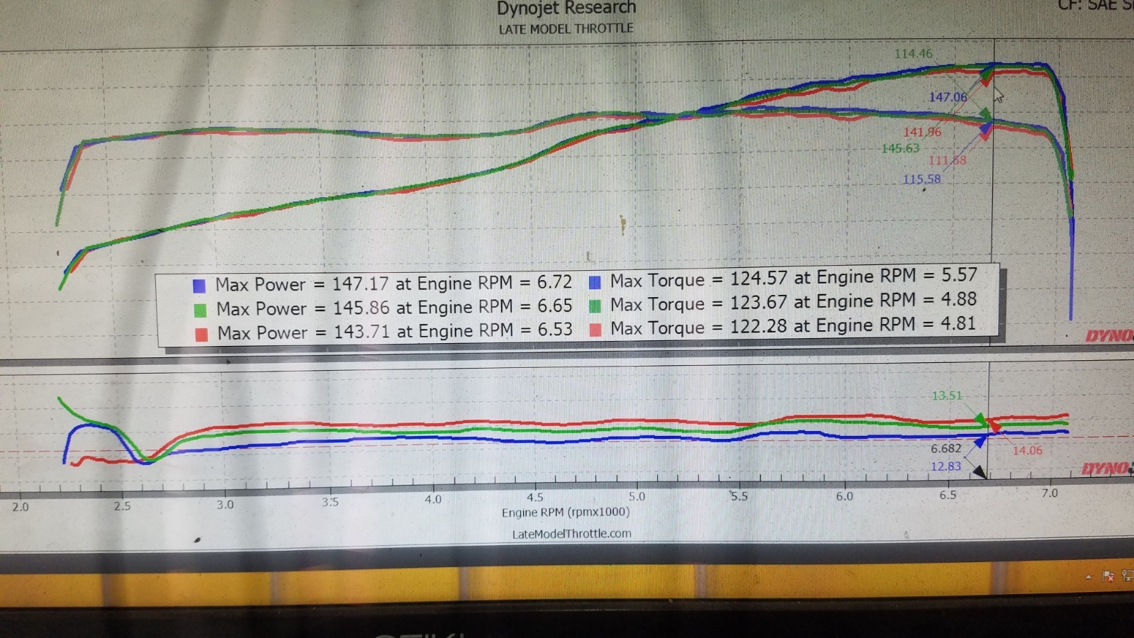
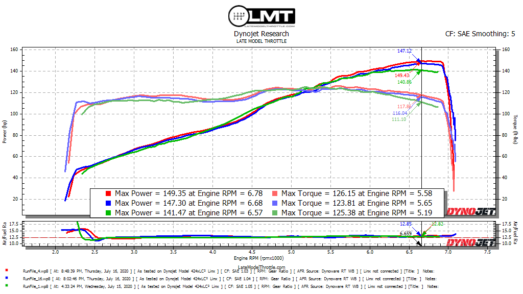
The amount of hype regarding the 21″ intake length was too much to ignore and we decided to redesign our entire airbox area to accommodate a nice smooth radius 21″ intake. On the dyno however, it was clear that the magical 21″ intake is not all its cracked up to be atleast with our engine and the SKUNK manifold.
GREEN: K&N 2.5″ Filter 9080 – Attached directly to the throttle body.
ORANGE: The Magical 21″ intake with K&N 9080 Filter.
BLUE: The Magical 21″ intake with an additional 16″ 90 degree intake tube (So 270 degrees of bends and 37″ total length) K&N 9080
RED: 16″ 90 degree shorty intake tube with K&N 9080 Filter.
NOTE the torque differences 4500 to 5500.
We also tested while covering about 25% of the filter area and there was no change in power, this was to learn whether the filter was able to flow enough, since its relatively small compared to others.
These runs were repeated about three times back to back changing configurations each time and the results were nearly identical each time.
Intake Manifold
With the change from an aftermarket to a modified stock header we gained back 25pts. The Skunk2 intake manifold seems to be worth about 6 to 7rwhp with our build with torque dropping slighting at 4000, but increasing at 4500 rpm and beyond. A plenum spacer would likely be the next modification to start the torque increase sooner.
The Skunk2 is not worth trading points for vs. a header, unless you needed to go to a side exhaust. The dyno plot below compares the Skunk2 dyno with JDM Tri-Y vs. the stock intake manifold and RB header with Kooks Exhaust. Notice the 10ft lb drop at 4400 RPM
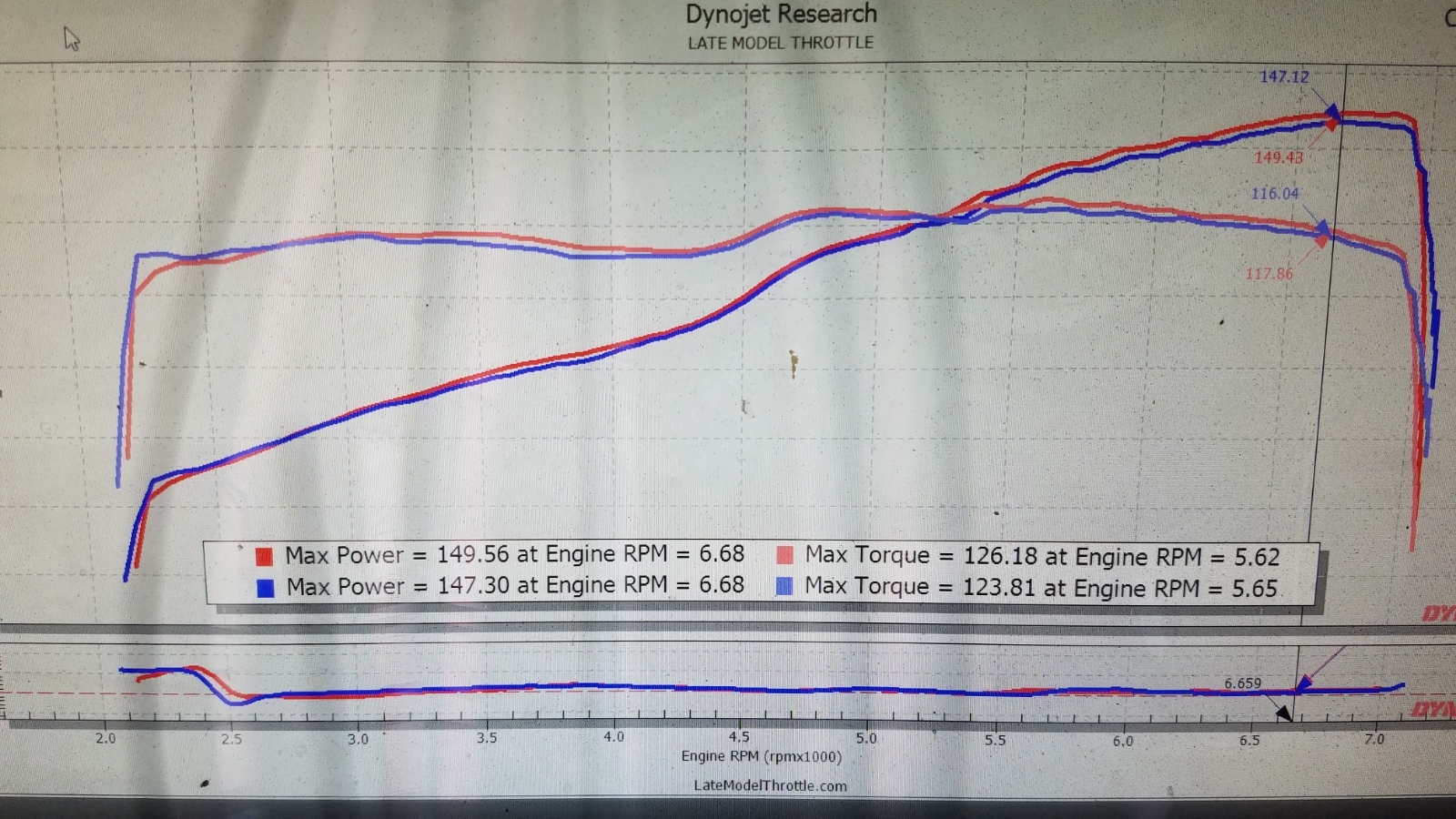
VICS vs. Skunk2
Moving from the stock JDM VICS manifold (Not square top) to the Skunk2 resulted in trading torque at different RPM ranges. Torque differentials would likely diverge more in higher RPM ranges, but for endurance race applications, its unlikely that the Skunk2 manifold would be better than stock.
BLUE – Skunk2 (Muffler) – More Torque after 6250
RED – Skunk2 (No Muffler)
GREEN – VICS (Muffler) – More Torque 4200-4700
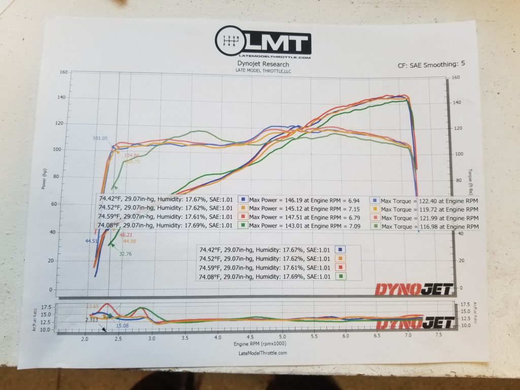
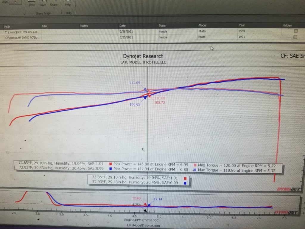
Skunk2 vs. Squaretop
In an effort to eliminate the torque hole that appeared at ~4200 RPM, I purchased a squaretop manifold and went to the dyno.
BLUE: Squaretop Manifold
RED: Skunk2 Manifold.
In short the manifolds perform almost the same, except the Skunk2 actually has better torque performance in the area were were trying to optimize.
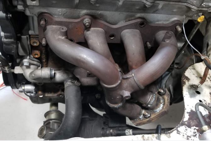
Exhaust/Header
In the early 2000’s we researched headers for our STS Mazda Miata. Out of all the options on the market, the Racing Beat 4-1 was the option that produced the best torque and most power. Nearly two decades later, there are only a few additional options on the market and the Racing Beat 4-1 still seems like the best option outside of exotic products of which we are unsure of reliability.
Spec Miata drove significant development into the ideal exhaust to maximize power within the SM rule set. From that solutions like the Kooks and Springfield Dyno rain supreme with top teams. We started with a Springfield dyno exhaust, but had issues with the welds cracking and decided to build a more reliable solution. The custom exhaust we had built utilized 2.5″ piping versus the 2.25″ of the SM exhaust. Although this exhaust was more robust, the builder put a bend in directly after the header which we were uncomfortable with from a power perspective. We’ve also received many complaints that our exhaust was too loud. As a result we purchased the Kooks exhaust, although loud, there is still a noise reduction from the Springfield dyno and our custom exhaust. We’ve also produced good power numbers and have not had any reliability issues to date with it.
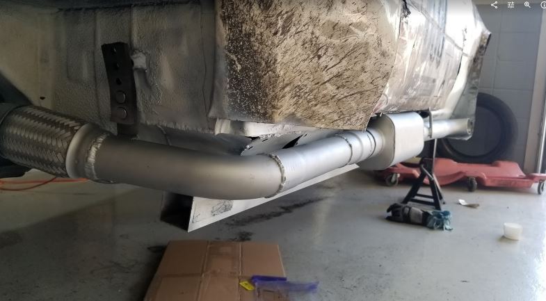
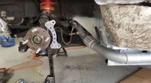
Updated Exhaust/Header
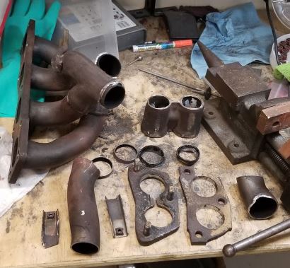
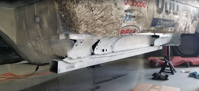
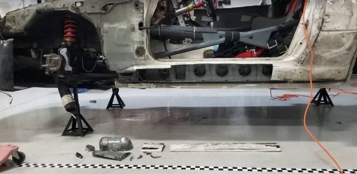
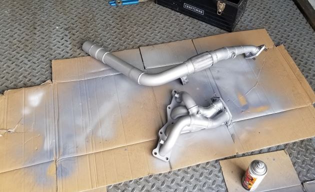
With the addition of a flat-floor heat became a major concern for the differential and transmission reliability. To resolve this issue we modified our JDM Tri-Y header to become a side mount exhaust. For routing clearance we removed the outter wall of the side-sill, flipped the removed components and rewelded to create a concave sill, vs. convex. This allows clearance for a small muffler to be routed along the side.
On the Dyno we found that the removal of the Racing Beat 4 to 1 header and Kooks exhaust cost about 6-8 rwhp from our previous dyno tune with no muffler. Adding the long Flowmaster HP2 costs another 2hp, while the short version of the Flowmaster HP2 only reduces power about a horsepower.
Because we went back to a stock manifold we were able to gain back 25 points to use on an intake manifold. The Skunk2 manifold was able to gain back almost all the power that we lost from switching our exhaust setup.
Aero
With the Miata there are plenty of gains to be had with smart a smart aero package that has the net effect of reducing drag, eliminating lift, and generating downforce. At the amature level aero is a bit of a black art. There is some CFD analysis but even the best CFD isn’t one-hundred percent accurate. We do our best to test on the track and gather data from the most reliable sources we can to develop our aero package. The aero package consists of large elements like: Splitter & Air Dam, Wing, Diffuser, Fastback, Flat Bottom/Floor, Side Skirts, but also smaller elements like mirrors, air deflection over window openings, seam taping, ect.
Aero should be treated like a package. Changing one element generally has an impact on others. In total we want to reduce lift, produce downforce, and reduce drag all while keeping the car in balance. Balance is the key element. An unbalanced car will be slower. We’ve lost only the wing and only the splitter and the results were lap times that were 4 seconds a lap slower.
Splitter & Air Dam
Empirically Air Dams reduce drag by decreasing the size of the high pressure zone in the front of the car. When a splitter is added this high pressure zone can be used to generate downforce by pushing downward on the lip of the splitter, while the back of the splitter, if raked appropriately can generate low pressure on the leading side of the splitter. Sources we used for the development included this CFD analysis and on the miata turbo forum. Gleaning information from these sources we believed the large airdam & splitter combo would provide the least drag and most downforce.
Splitter/Airdam Progression

Revision 1
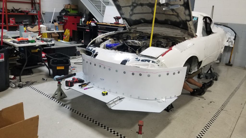
Was build from 3/8″ birch plywood for the splitter, 0.070″ thick HDPE for the airdam, and no-dig edging to connect the two together. We cut the front bumper just below the indent and riveted the HDPE into the bumper. Initially we built a structure to attach the airdam to the radiator supports, then used a cable to adjust the front height. The idea is that, when we hit something, the splitter could flex upward without breaking any of the supports. The splitter lacked stability so then we used longer rack bolts and put them through the splitter. Mounting was greatly improved with later designs. You can also see the airdam itself pushed inward. This is limited with the addition of brake duct structure and new radiator ducting.

Revision 2
After the first race, the splitter performed well but we wanted to reduce weight and add better mounting. The bottom of the splitter was in good condition, so we thought we could go with a material like Alumalite to save weight. The second revision of the splitter was built from 6mm(1/4″) alumalite which was purchased as scratch and dent from a local sign supplier for $50. We also extended the mounts further back and ran two 7/16″ bolts through the main subframe holes This provides enough strength to stop the wing from any yaw movement. We retain the flexible front design with a light weight chain attached to a bolt though the splitter. Alumalite will delaminate on the edges, so we added a 1/8″ thick, 1/4″ Aluminum U channel attached to the leading edge of the splitter with construction adhesive and metal zip ties. Other than a wall contact, the splitter has held up great, incurring more damage on Dyno’s and getting in the trailer than on the track.

Revision 2.5
In subsequent races we added more material to better contour around the tires. We’ve also flared out the edges of the airdam closer to the edge of the splitter to deflect this air. We did receive information that chapter 9 from Race Car Aerodynamics covers a windtunnel test with an integra where adding vertical fences in front of their tires doubled downforce on their splitter. We replicated this design, but we have not been able to get conclusive data on this design modification as of yet.

We’ve tested splitter extensions of 4″, 5″ and in excess of 5″. There is not a considerable difference in our tests between these sizes, in drag nor downforce, however we will be moving back to 5″ in new designs since we believe the potential for downforce is greater than the potential for drag. An alumalite splitter was a few pounds lighter than its smaller birch counterpart.
For the radiator opening, we used a source that indicated an opening equal to 1/3rd the size of the radiator we have had cooling issues, but we do not know if this was a factor. We’ve found more success when we seal the passage from the airdam to the radiator. This helps direct the high pressure zone through the radiator. We are also using this zone for our intake.
We’ve only completed one event without the splitter which was VIR south. On the course the splitter/airdam combination was about 0.4 seconds per lap faster than without it. We know some of that was due to an increase in drag and reduction in straight line acceleration. There was also a change in handling although outright lateral grip was not noticeably impacted.
Revision 3 (On Right)
We’ve begun to add front diffusers to the splitter to increase the downforce. Unfortunately this design reduced the strength of the alumalite along with the increased downforce, caused the splitter to loose strength and contact the ground under heavy breaking. It also began to unevenly cool the inside face of the rotor causing cracking.
Revision 4
We’ve increased the overall size, the size of the splitter diffusers in an effort to increase performance in yaw. We’ve also added a second reinforcement layer of alumalite to stiffen the leading edge and added front supports. To counter the increase in airflow over the inside brake rotor face, we’ve added “dust shields” with a hole near the rotor center for our brake cooling ducts. This evened out the cooling and the rotors performed very well with this method.
Charged Splitter
We’ve added a 1.5″ rise in the center of the splitter in order to help solve an issue with the diffuser losing downforce in yaw. This did seem to help, although this rise will be lowered to 0.75″ for further testing.
Foot Plates
Multiple foot plates were tested at Gingerman. Large send plates enclosing the side area of the difusser and airdam produced significant drag, and didn’t appear to generate significantly more downforce, although manometer readings were substantially higher, it is beleived that the area of low pressure changed.
More modest end plates seemed to increase downforce without a significant increase in drag.
Splitter Diffusers
Two large splitter diffusers were added following Professional Awesome’s design. These were installed along with venting the tops of the front fenders. The result is the feeling of more downforce and a significant change in air flow in the wheel well area, so much so that the rotor cracked within a 20 minute session due to un-even cooling on the inside rotor face. A shield was added to block air from these diffusers from hitting the rotor face while allowing the central rotor cooling duct to supply air through the rotor vanes.
Splitter Blocks
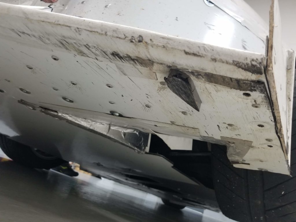
After ruining our splitter edge due to contacting the ground at Road America during testing, we’ve invested in titanium splitter blocks which have taken considerable punishment and worked great at protecting our splitter. They also helped in dialing in ride height and splitter height without worrying about damaging the splitter. You can hear them scraping the ground when contact is made and that sound can be used to inform decisions on splitter and ride height.
Splitter Template
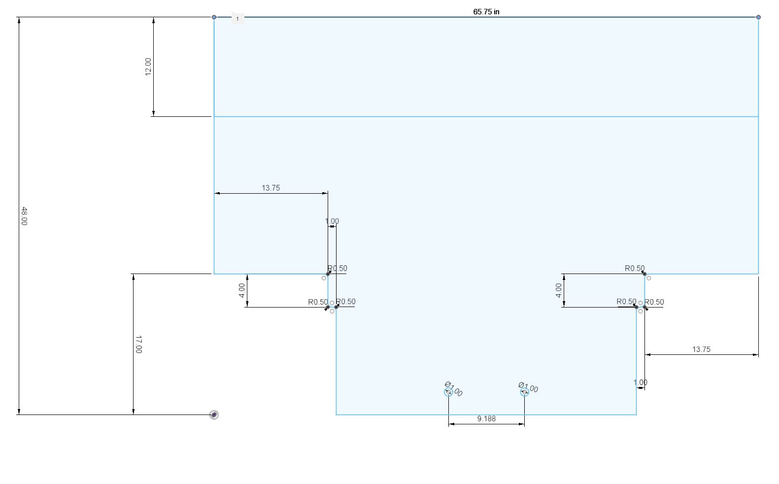
The following dimensions are used to create a template for a splitter that bolts through the subframe with two bolts in the rear and extends 12″ in front of the front bumber. This can be trimmed once the airdam is attached. This template clears 15x10s with 245/40-15s and 25mm offsets.
Our next splitter will be made from 10mm alumalite (pro-lite) vs. the 6mm alumalite.
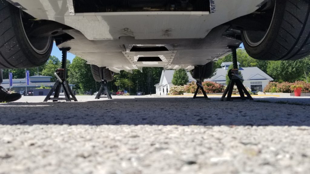
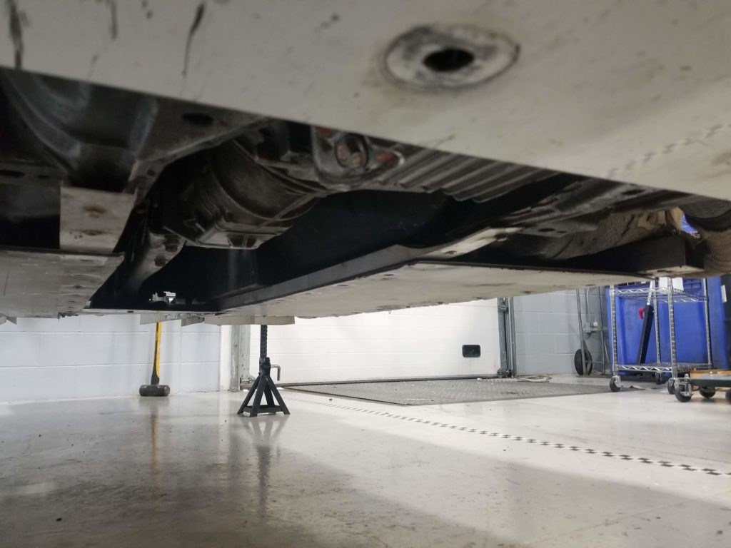
Flat Floor
The initial debut of the flat floor with the OE exhaust routing showed little promise in controlling transmission and differential temperatures. Despite wrapping the exhaust, removing the main central floor panel and 40 degree ambient temperatures, transmission and differential temperatures were still concerning. The only reasonable solution was to move to a side exhaust which required a customized header, mid-pipe, and significant modification to the drivers sill. Was it worth it? Probably not, but we did it anyway and I will share our findings.
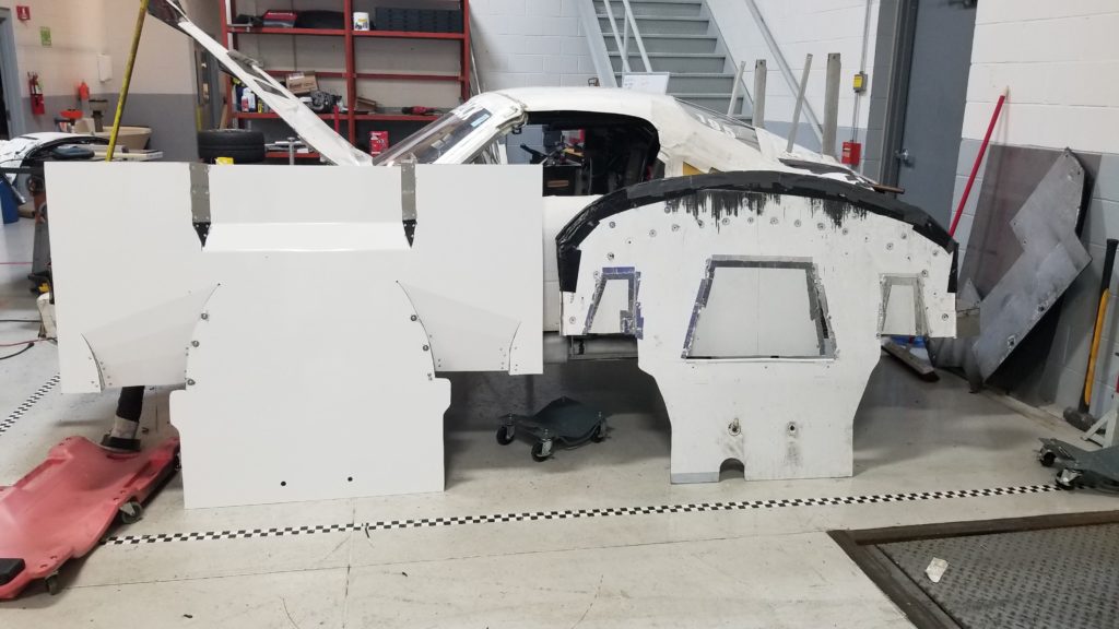
Flat Floor Panels
The entire flat floor is comprised on the following panels.
Splitter – Alumalite construction covers the full width of the car from the front of the bumper to the axle centers.
Engine Panel – 0.062″ Aluminum, Covers the transition from the splitter to the frame rails. and covers the full width of the car. Features a small diffuser under the oil pan to direct air at the transmission. This diffuser was added after testing and seems to cool the transmission a handful of degrees more than without it.
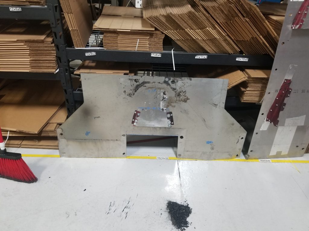
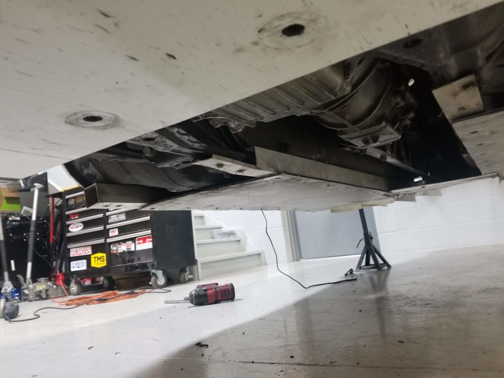
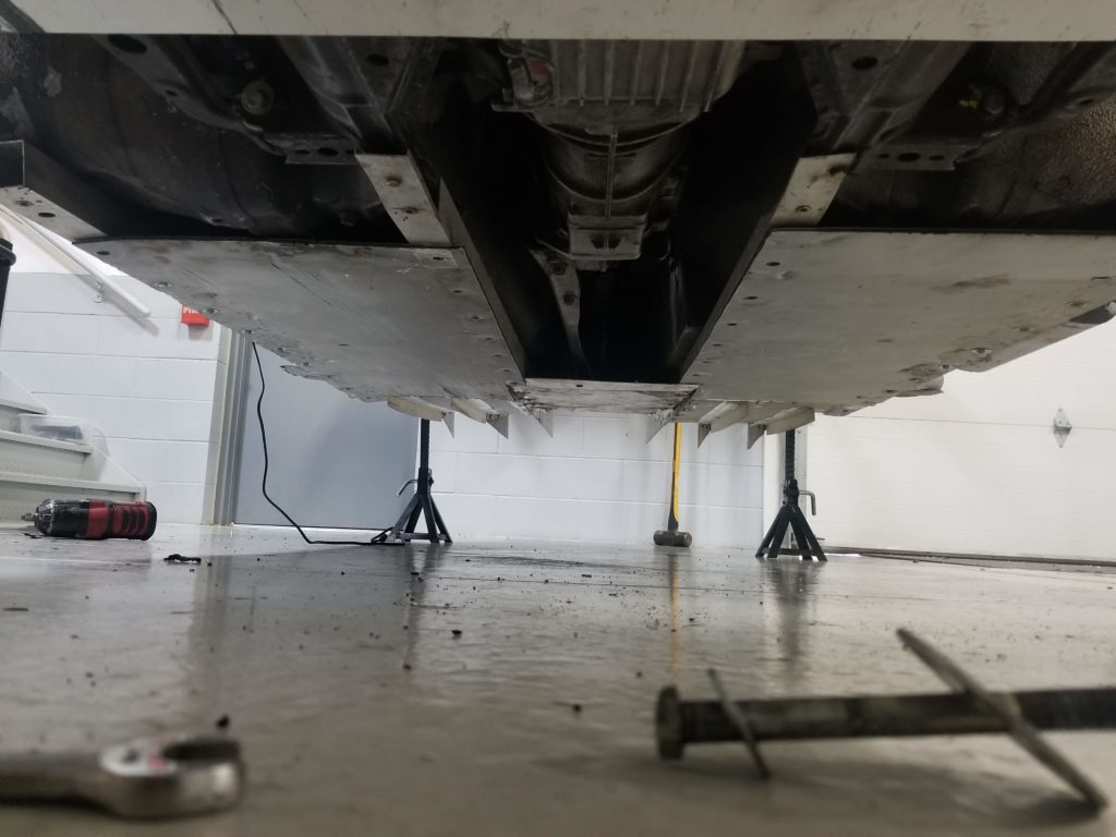
Three Central Panels – A drivers and passenger side panel (Alumalite) extend from the engine panel all the way back to the long diffuser throat. A central panel is make of 0.062″ aluminum and has a mid-transmission diffuser and a rear transmission diffuser to cool the differential. The differential is always about 10 degrees cooler than the transmission with this configuration.
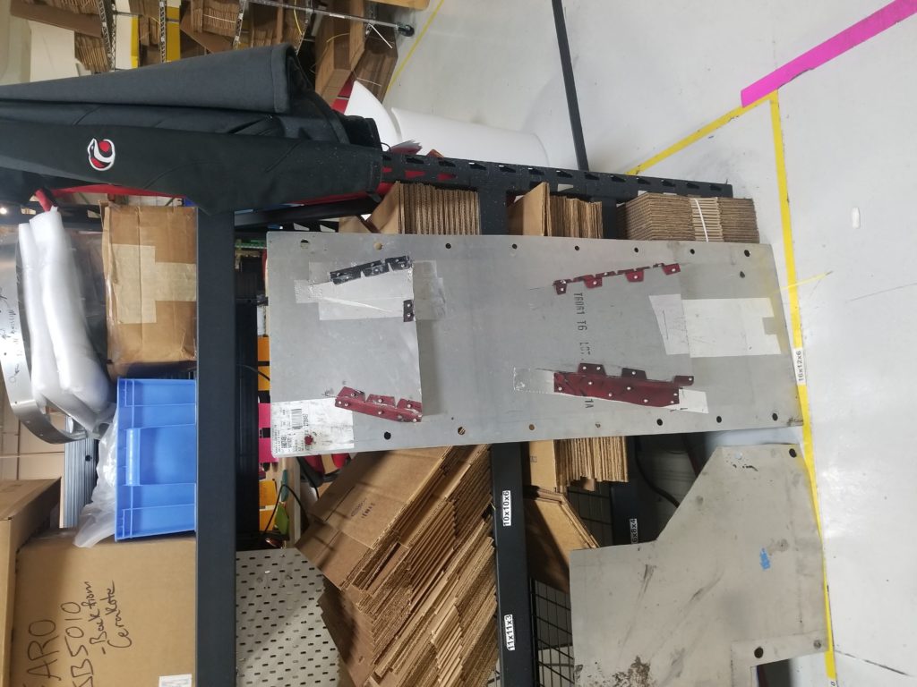
Three Long Diffuser Panels – Two alumalite panels on the drivers and passenger sides extend from the cabin frame rails, under the a-arms, and slope upward out the rear. A central 0.062″ aluminum panel starts its ramp 14″ ahead of the diffuser resulting in a much larger central channel.
All panels overlap with the forward panel overlapping the panel behind, with the central aluminum channels being installed on top of the alumalite side channels. This makes it easier to just remove the central panels for most maintenance and protects the panel edges. So far scraping has wore down screw heads and damaged some panels, but not to a degree where it would impact performance. Regular replacement of hardware and periodic replacement of panels should take place.
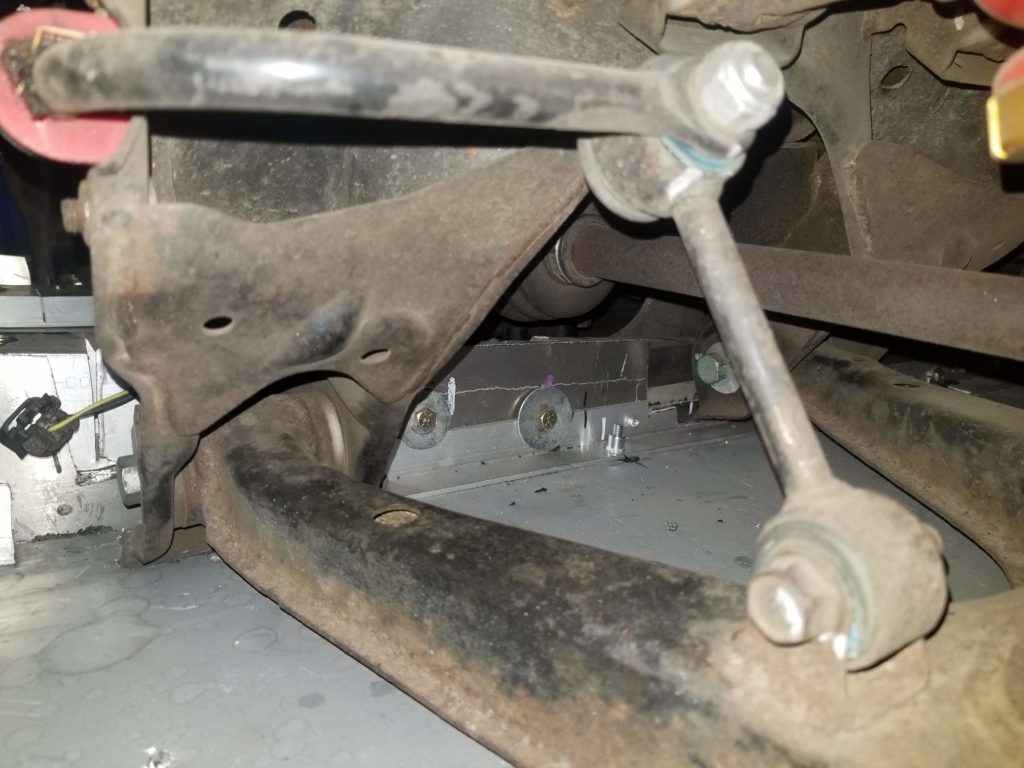
Flat Floor Mounting
Four rails are installed, two along the pinch welds, and two from the front subframe to the end of the diffuser (past the rear subframe). The rails are installed using rivnuts installed in the chassis with grade 8 hardware, then rivnuts installed in the rails themselves with grade 3 hardware to hold the panels to the rails. Rails are made from thin wall aluminum square stock (1.5″) except for the inside drivers side channel due to the lowered floor. This channel is only 1/2″ high to maintain a flat height across the rails.
If I were to do it again I would use thin wall steel channel and weld them to the chassis and sub-frames. This would improve rigidity without a significant weight penalty, especially when the panels are tightened it would effectively box in the chassis. It would also provide a more robust material for jacking up the car. We did make a set of replacement rails but so far the initial rails have held up very well to abuse and are protected by the panels.
A small peice of steel was welded across the rear subframe fore and aft arms to support the central rails and help control the angle of the diffuser. This was also integrated into much larger central strakes made from 0.062″ aluminum.
Diffuser
We were running an R-Theory V3 diffuser prior to our flat floor, however we do not have data on whether the diffuser improves performance, except that it does not noticeably decrease performance. We believe there are several design flaws with this diffuser especially for track use. The front tabs have proven weak and have broken several times. The vanes are held to the deck via “L” brackets attached with screws, we believe this introduces drag.
Custom Diffuser
Diffusers generate low pressure at the throat of the diffuser. When used with the flat floor they can also lower the pressure of the entire floor and even impact the splitter. Our goal is to move the diffuser throat as far forward as possible. Allow for maximum expansion at the back of the diffuser, and control rear tire wake. Based on CFD from an FRS by Versus Engineering we can see that the center of the car has the best supply of air to use so we wanted to opimize our central diffuser channel. Due to the design of the a-arms on the miata we are also limited on what we can do with the side channels on the diffuser.
Various sources online say that around 8 degrees is a pretty safe diffuser angle without CFD or testing. We designed out diffuser to ramp from about 4 degrees up to 8 degrees at the back with the option to increase that up to 14 degrees on the sides and over 20 degrees on the central channel. There is also research that indicates expansion angle is very dependent on ride height. The higher the ride height, the more angle that can be supported without the vortexes inside the diffuser bursting and losing downforce and creating drag.
Radius’ed turn ups are contrary to popular information online, however we added them per the testing by versus engineering on their FRS and because this type of radius is becoming much more common on new cars.
Strakes
We added additional strakes to the diffuser to help capture and control the tire wake, or tire squirt formed by the rear tires. We wanted strakes that could help block that flow from entering our center channel and messing up our air. These strakes are extended forward of the rear tire. No CFD or testing was done, and this was done solely on the basis that rear tire squirt is a big deal and needs to be blocked. We plan to extend our strakes further down, because they don’t need as much clearance as they currently have with our ride height. Strakes that can be damaged are a flexible plastic, and our higher strakes are made from 0.062″ aluminum and attached with an aluminum L-Channel.
Overall it seems the diffuser generates about 50% to 75% of the rear bias downforce as our nine lives racing wing. Its possible that the diffuser is responsible for considerably more downforce but its much more front bias’ed than our wing. Additional testing would be needed.
Wing
Wings are the easy button and an important part to tuning your aero balance. Easy adjustment of angle of attack, adding gurney flaps or a second element and quick and easy ways to balance the rear of the car with any aero changes elsewhere on the car. There are some wings advertised with very good lift to drag ratios. Those are actually about half the advertised lift/drag ratios that they advertise. I’ve been told that Wingmen Aero Group offers really good and efficient wings.
ChampCar rules prohibit carbon fiber, which greatly limits the number of wing options available. You either have to make your own, buy from a niche supplier who builds small batch or custom wings.
 Our first revision of the wing had large adjustment plates which allowed us to position the wing different distances on the rear and also allowed us to adjust AOA (pitch) of the wing. We cross braced this wing with 1/16″ cable supports which went between the bottom left to the top right and vice-versa. This arrangement was fine at Road America which is a smooth track, but the cables broke at Sebring due to the stress in bumpy corners.

On the next revision we wanted to reduce drag, allow for a DRS feature in the future, and increase strength. In researching the drag of shapes, it was clear a streamlined body, even with a much larger cross sectional area would result in less drag. In fact a round object produces 11.75x the drag of a streamlined object. Whats more a flat plate has a Cd between 0.8 and 1.3 which is roughly 20x the drag of a streamlined object. As such we located aluminum aircraft struts purchased a bunch of everything and began experimenting. Here is what we learned:
The small strut has the strength to support any wing size and if mounted firmly to the chassis, will not require any jury struts, or bracing. For our rear wing, we use two small struts, one which largely supports the weight of the wing, and a second strut which we use to adjust angle of attack (AOA). The strut itself is strong enough to support a bolt directly through it and the optional strut fittings are just added weight. We’ve also used the medium strut and welded it directly to the wing element with no support strut. We have yet to see a wing mounting design that is stronger than this type of design and are very happy with it thus far.
The rear wing has proven to be very necessary for our car. Without the wing, the car was 4.5 second slower at Sebring and much more difficult to control. This brought our times from some of the fastest ever by a ChampCar Miata at the track, to that of the other Miatas running that day without aero packages. When testing time is available we do however like to adjust AOA of the wing such that our drivers can stay flat on the throttle in key track sessions and have the stability under braking, while trimming out as much downforce, and thus drag, as possible. Optimal AOA settings have been between 0 and 8 degrees.
To ensure compliance with the 12″ rule that allows wings to be no more than 12″ above the highest part of the car we use an 8ft level and a 12″ object centered on the roof.
We had testing a front wing. It was awesome, but banned after about 3 laps.

Wing and Diffuser
If a wing is set-back far enough, it can help increase the low pressure zone behind the car and help suck more air through the diffuser and out from under the car impacting downforce overall. We’re currently testing a more rearward placement of the wing.
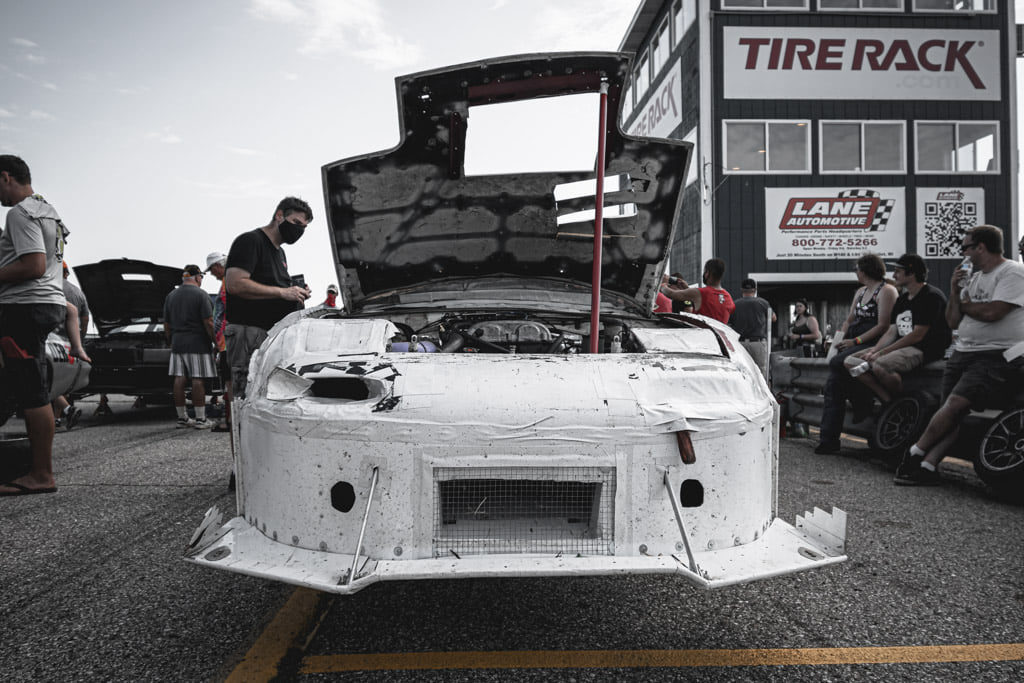
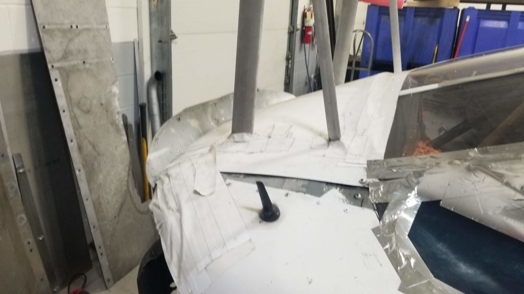
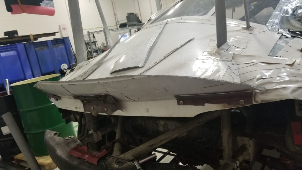
Fastback
 In an effort to reduce drag we analyzed the limited data available to us and determined that in addition to a flat floor, a fast back had the highest potential of increasing our performance. Research on the fastback is limited and sometimes conflicting, but in general it appears a fastback would reduce the size of the negative pressure zone on the back of the car. From analysis of the lowest Cd shapes, the ideal condition is one where we create a half tear drop out of the rear of the car. As such we began measuring to create this shape in a 3D profile.

ChampCar allows all top material which is in the stock hardtop location to be charged at zero points. We removed our treasure coast light weight hard top and installed a TCM chop top which is less expensive and didn’t require us to remove much material to meet our goal. We gutted our OEM trunk lid and removed the spot welds from the multiple sheets of sheet metal that hold the rear bodywork together. We then measured angles from the chop top to the rear of the car. From our research it seemed 15 degrees was the ideal angle to reduce drag.
The fastback was completed in time for Road America where could compare to our times in late 2018. Although we had fresh dyno results from both races, and similar but not identical suspension setups, we have a 5spd transmission vs. a 6spd at the time, we added a diffuser, and we were shifting at a higher RPM in the earlier race. Never the less our car was 0.48 seconds faster.
Spoiler
A zero point repurposed spoiler was added and tested. With a fast back the spoiler seemed to increase downforce/reduce lift, to the effect of about half a wing at zero degrees AOA, however we did end up creating much more drag than expected, perhaps even exceeding the drag of the wing itself. I believe this is due to our fastback already having the optimal streamlined angle to keep air attached.
Teams without a fast back should try a spoiler as it SHOULD reduce both rear end lift and reduce drag, sort of like a fastback. In general the angle of the spoiler shouldn’t matter much so long as you have ~14 degrees from the rearward peak of the roofline to the top of the spoiler which should be about 2-4″ on a stock miata.
Simulations
Using Optimum Lap and Mario’s base model I’ve modified to match the PartsBadger Car: https://occamsracers.com/ I’ve run some simulations based on Road America.
These simulations are actual weights and power numbers, but what is important is the delta times with each change.
- Base Lap: 2:33.83 Road America (Kink)
- 148RWHP
- 6850 RPM Max RPM
- 4.3 Diff
- 0.410 Drag
- 1.2 Df Coefficient)
- 4.1 Diff vs. 4.3 Diff = +0.15 seconds slower
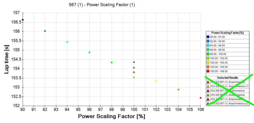
- 133rwhp = +2.87 seconds slower
- 136rwhp = +2.22 seconds slower
- 139rwhp = +1.62 seconds slower
- 142rwhp = +1.02 seconds slower
- 145rwhp = +0.47 seconds slower
- 148rwhp = baseline
- 151rwhp = -0.48 seconds faster
- 154rwhp = -0.98 seconds faster
- 157rwhp = -1.38 seconds faster
- 7050rpm vs. 6850rpm = -0.28 seconds faster
- 6585rpm vs. 6850rpm = +0.55 seconds slower
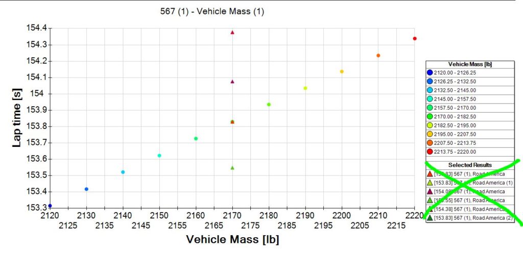
- 2120 = – 0.51 seconds faster
- 2130 = -0.41 seconds faster
- 2140 = -0.30 seconds faster
- 2150 = -0.20 seconds faster
- 2160 = -0.10 seconds faster
- 2170 = baseline (with driver 50% fuel)
- 2180 = +0.11 seconds slower
- 2190 = +0.21 seconds slower
- 2200 = +0.31 seconds slower
- 2210 = +0.41 seconds slower
- 2020 = +0.51 seconds slower
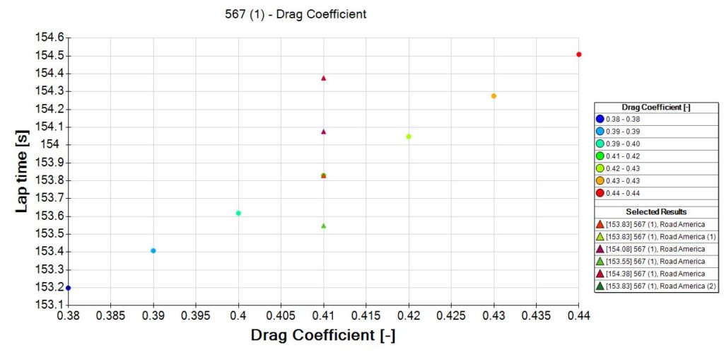
- 0.38 Cd = -0.63 seconds faster
- 0.39 Cd = -0.42 seconds faster
- 0.40 Cd = -0.21 seconds faster
- 0.41 Cd = baseline
- 0.42 Cd = +0.22 seconds slower
- 0.43 Cd = +0.45 seconds slower
- 0.44 Cd = +0.68 seconds slower
You can see what contributes to drag in Mario’s write up here: https://occamsracers.com/2021/02/10/where-drag-comes-from-on-a-miata/
- 6spd Transmission vs. 5spd = -0.34 seconds faster